UCC has a S-100 Alpha Micro system (known in UCC history as Murphy) which [FVP] is working on restoring back to working order (as of July 2021). aka "How not to restore old computers" - [MPT]
This page will be kept up to date with details of the restoration work. The process is mostly inspect - test - [explode] - fix - repeat, the results of which are presented below. [FVP] is not currently an expert in restoring vintage electronics and has a habit of breaking things. More info will be added as more stuff gets tested, hopefully not blown up, and (eventually) fixed.
For more UCC-specific history of Murphy, please see: ProjectWhatIsThat/Murphy, https://www.ucc.asn.au/machines/murphy.ucc
Amazingly there is quite a significant amount of online resources (including extensive scanned documentation) for just about everything S-100 related. See the lists below for details and links.
What bits are there
- ACP "Alpha16" wooden box computer case
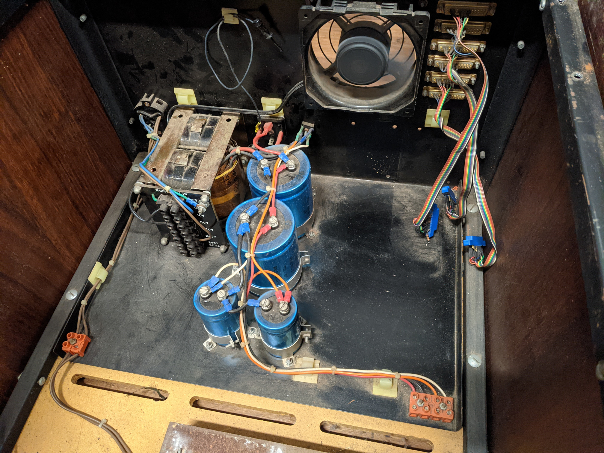
- an unregulated 250V transformer-rectifier-capacitor style +8V/-8V/+16V power supply (built into the wooden case) - suspected working
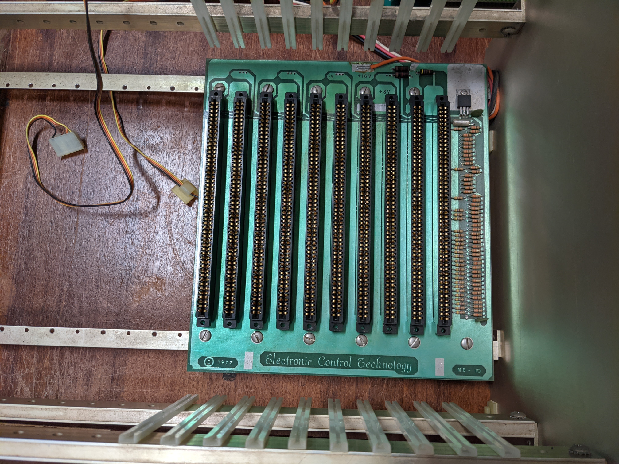
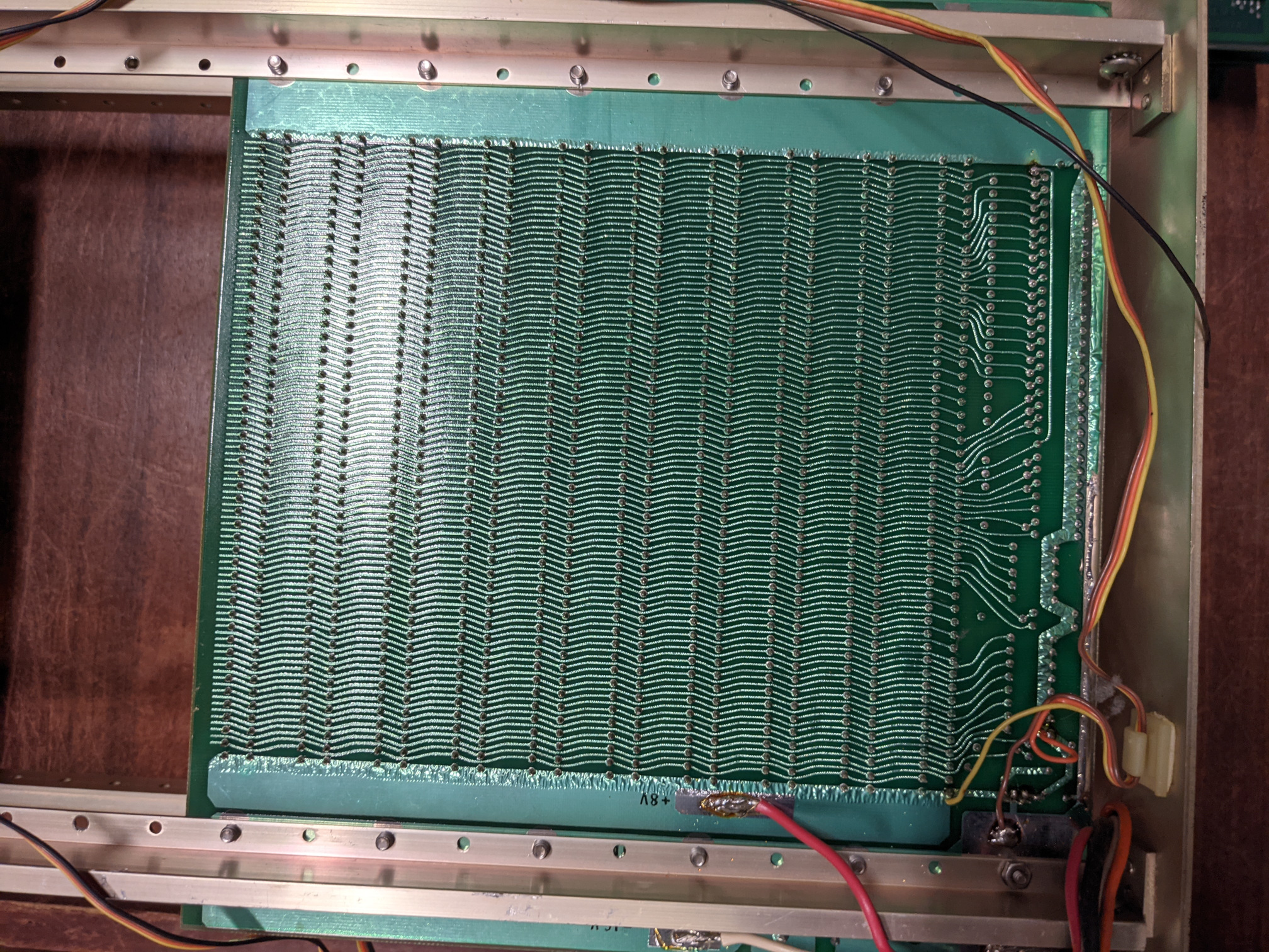
- Electronic Control Technology MB-10 10 slot S-100 backplane (copyright 1977) - suspected working
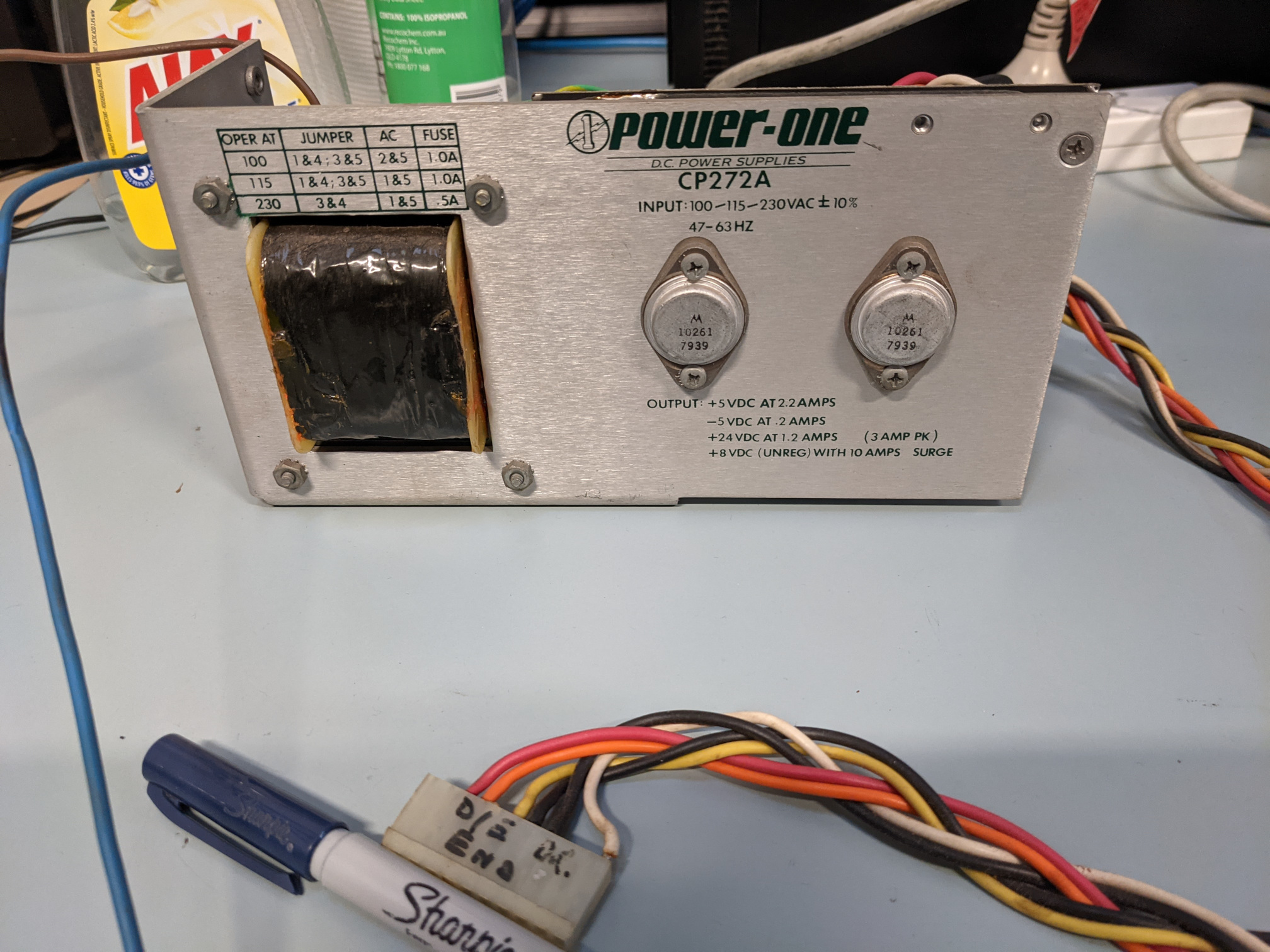
- Power-One CP272A switchmode DC power supply - outputs are +5V @ 2.2A, -5V @ 0.2A, +24V @ 1.2A, +8V @ 10A (surge, unregulated) - for Persci drives - not working
- tested with power on with no load - output voltages were correct (initial test before explosions)
- tested with drive connected - catastrophic failure involving multiple component explosions - need replacement components
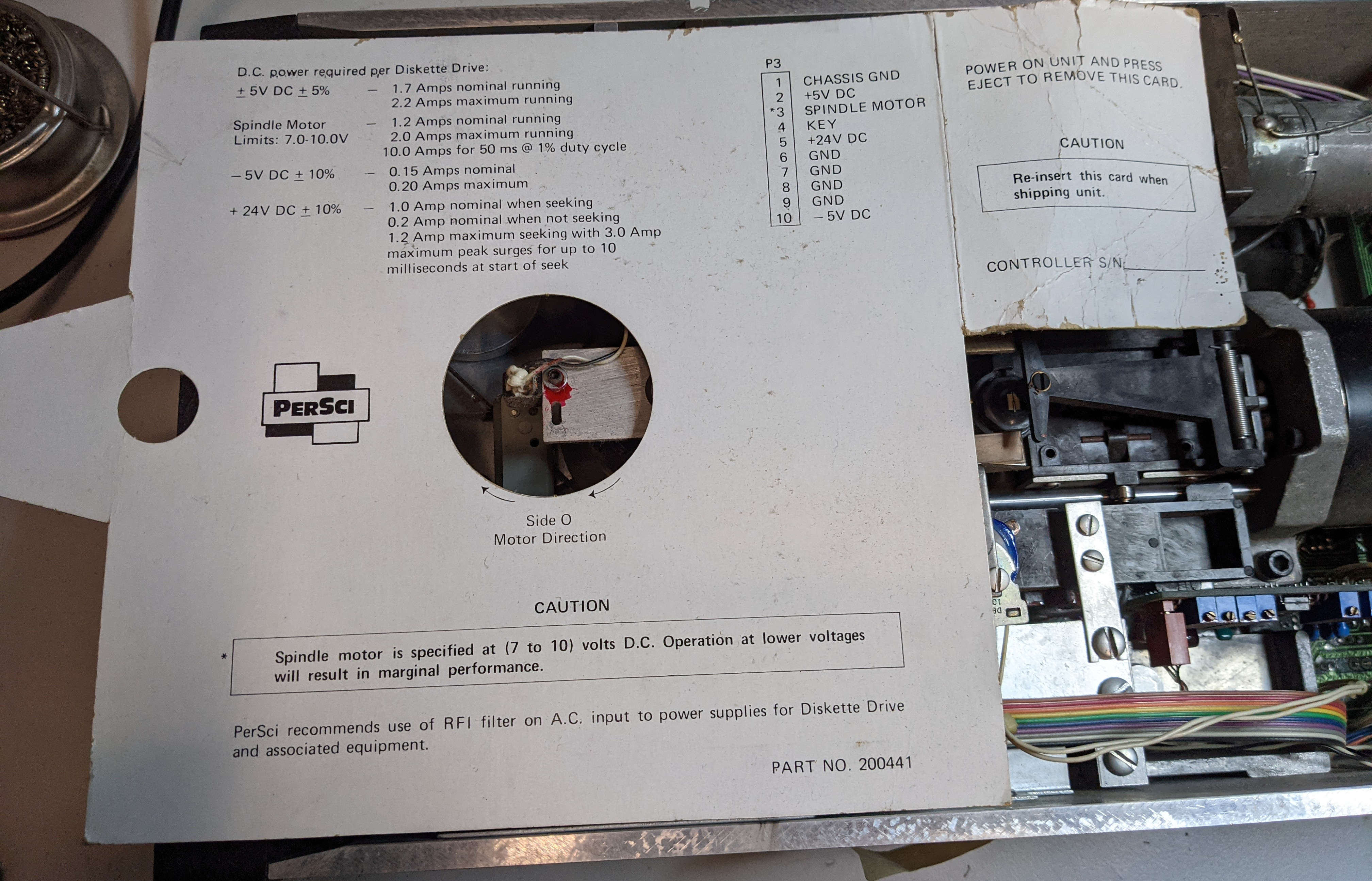
Persci 277 dual 8" single-sided voice-coil-actuated double-density floppy drive - not working Installation & Maintenance Manual Logic & Schematic diagrams
tested with "working" original PSU - multiple PCB components exploded simultaneously, need some replacement parts & more testing
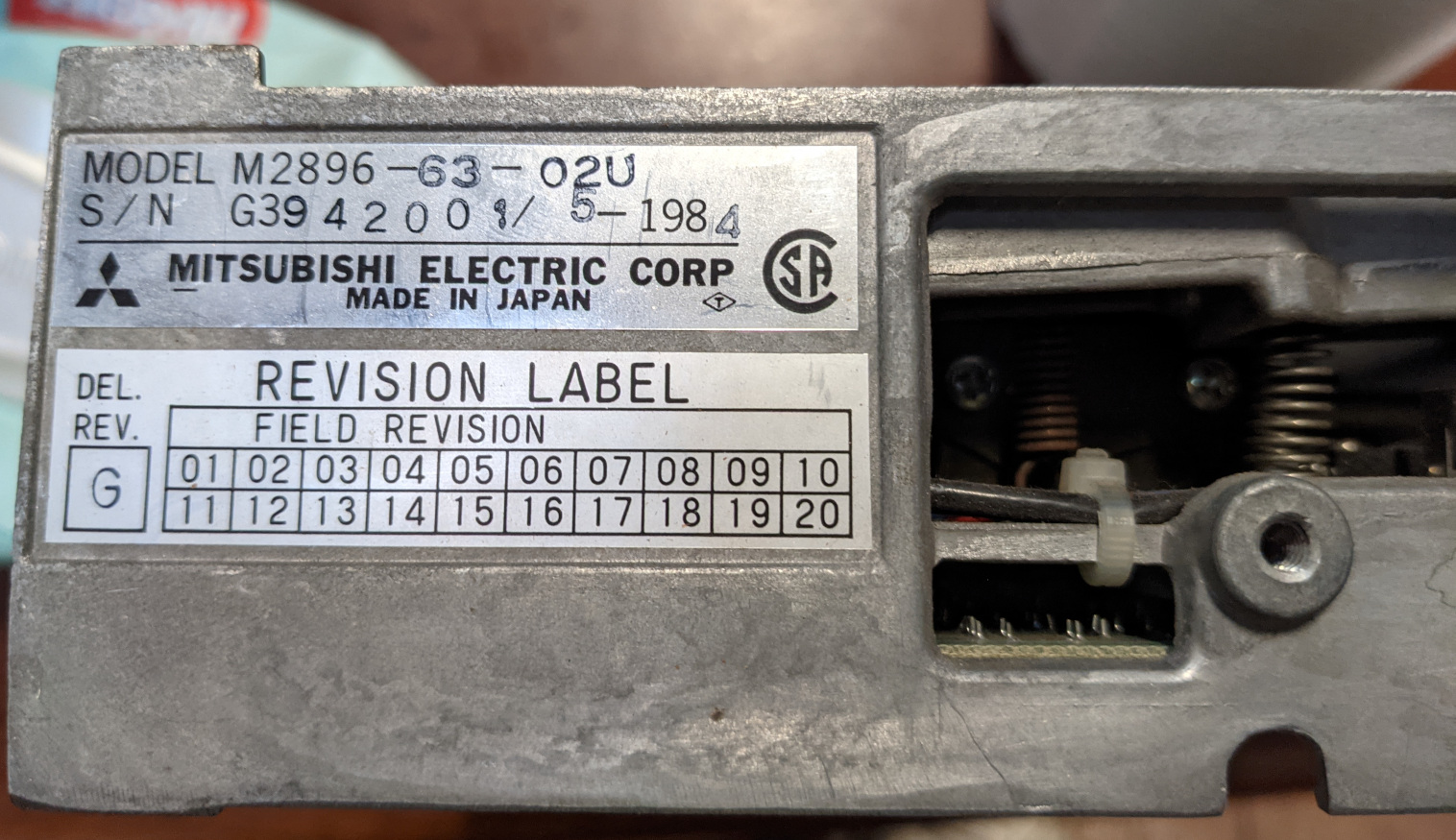
- Mitsubishi M2896 Rev.G 8" floppy drive S/N G3942001 (loose in box) - suspected to be a random leftover part from some other computer build (dated 1984) - untested
- ACP Terminal (builtin monitor + keyboard combo) - suspected not working (tested in 2019? - white dot on screen or no display at all)
S-100 Cards
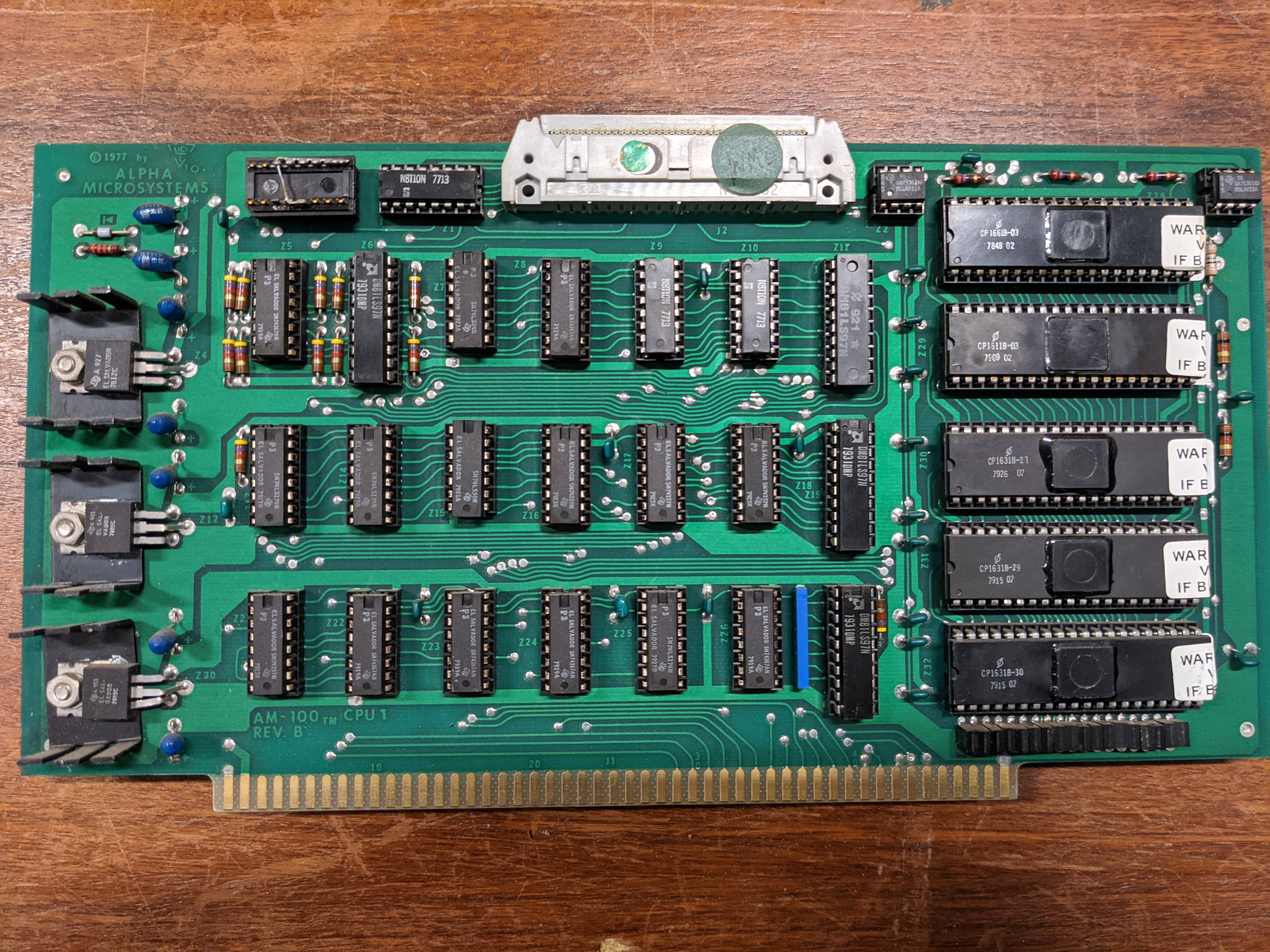
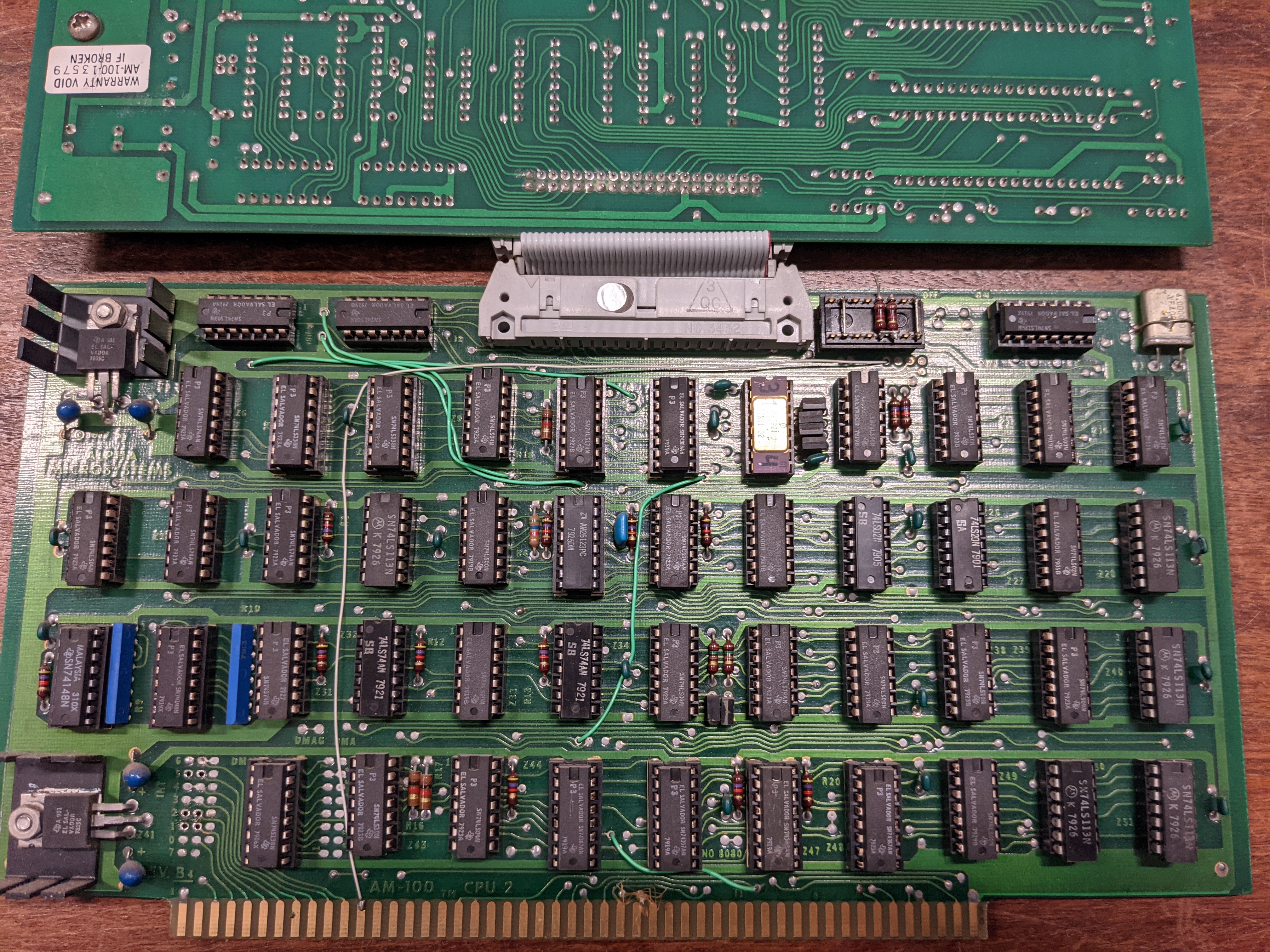
Alpha Microsystems AM-100 16-bit CPU (set of 2 cards) (1977) - untested Tech Manual Instruction Set Ref
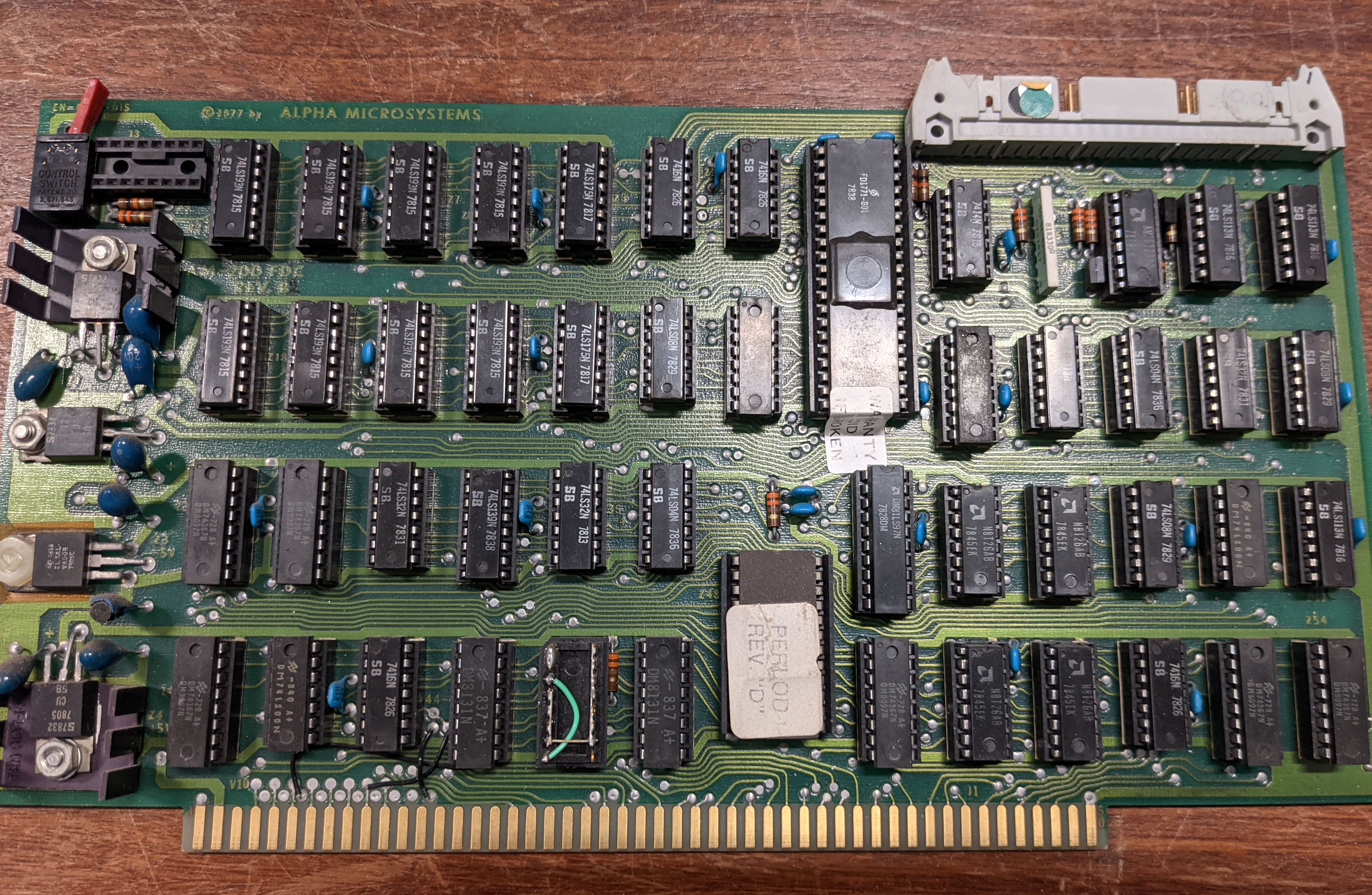
Alpha Microsystems AM-200 Floppy Disk Controller Rev B (1977) - untested Tech Ref(?)
Alpha Microsystems AM-300 6 channel Serial IO board (1977) - untested Mixed Docs + Schematics Technical Manual
4 * Industrial Micro Systems IMS C00282 16K Static RAM Memory boards (1977) - untested Manual
- Australian Computer Products diagnostic board(?) - no part number, includes an enlarged UV mask which probably was used to design/manufacture the PCB itself
Disk Drives
At some point it would be nice to run the 8" Persci drive using a Greaseweazle to try reading data off the club's box of 8" floppy disks. Assuming the drive unit itself can ever be restored to (somewhat) working order, the Greaseweazle should be able to control it with some custom wiring or something like the FDADAP to connect the standard 34-pin PC floppy cable signals to the Persci 277's 50-pin connector.
Specs for the Persci 277 drive are here.
Persci 277 repair notes
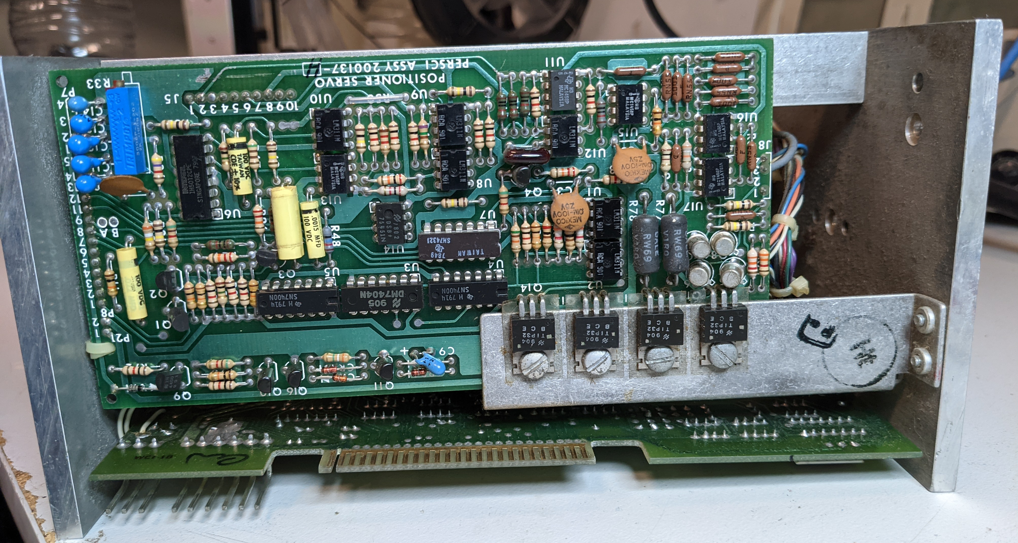
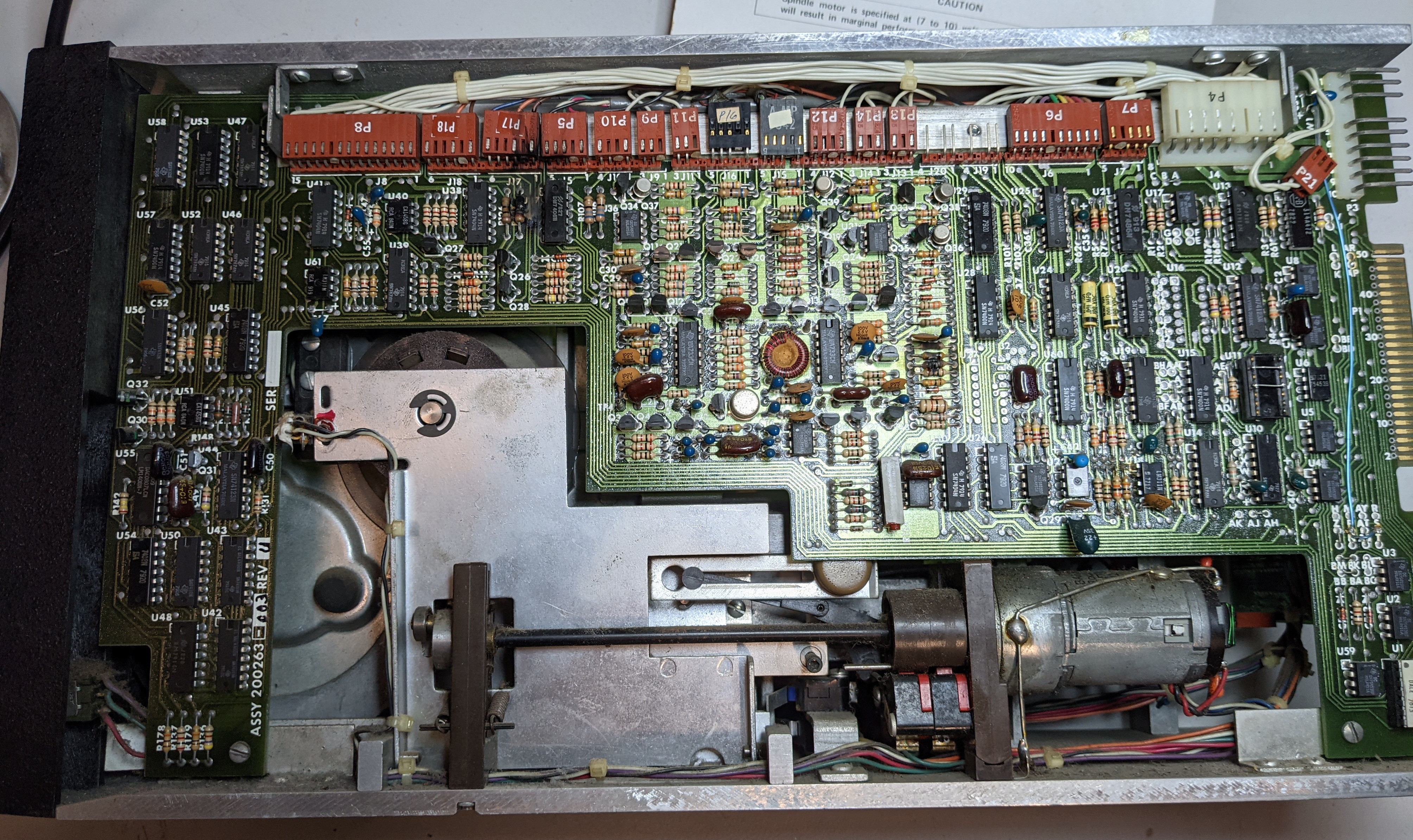
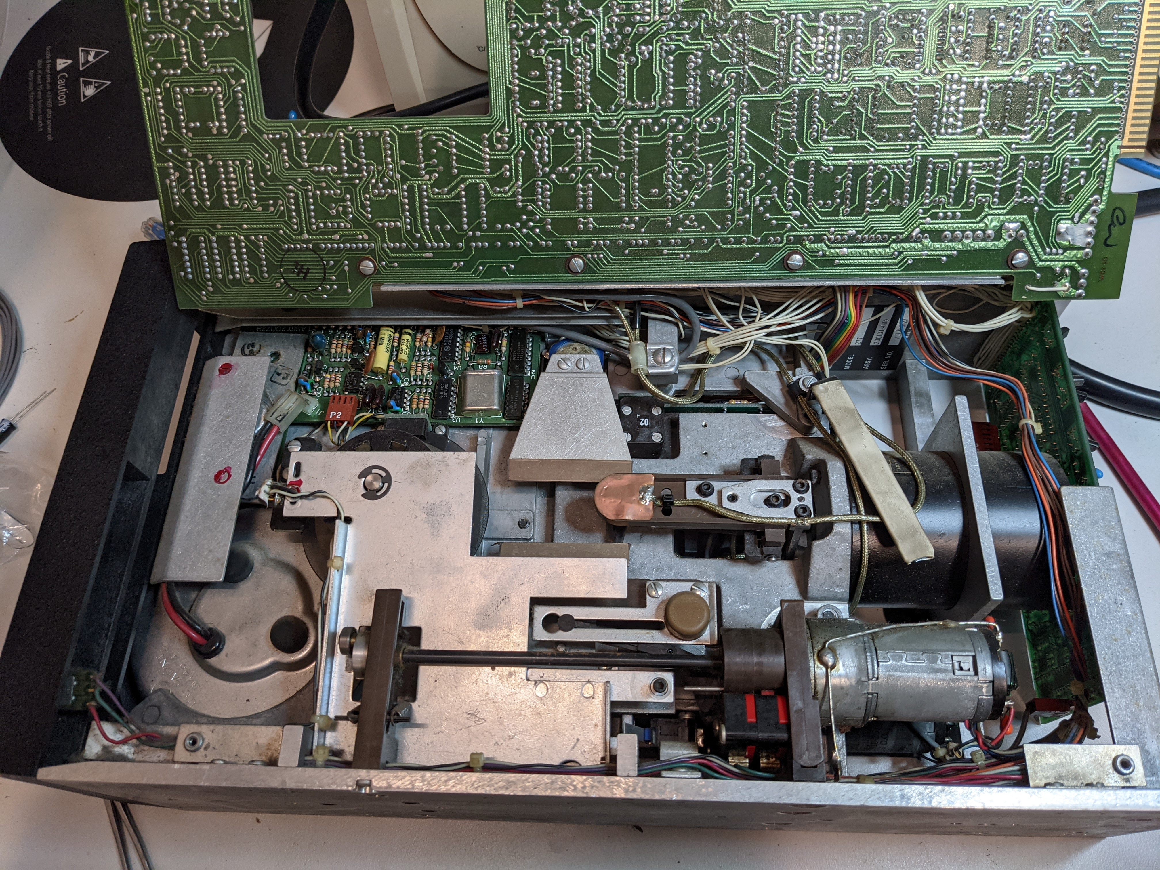
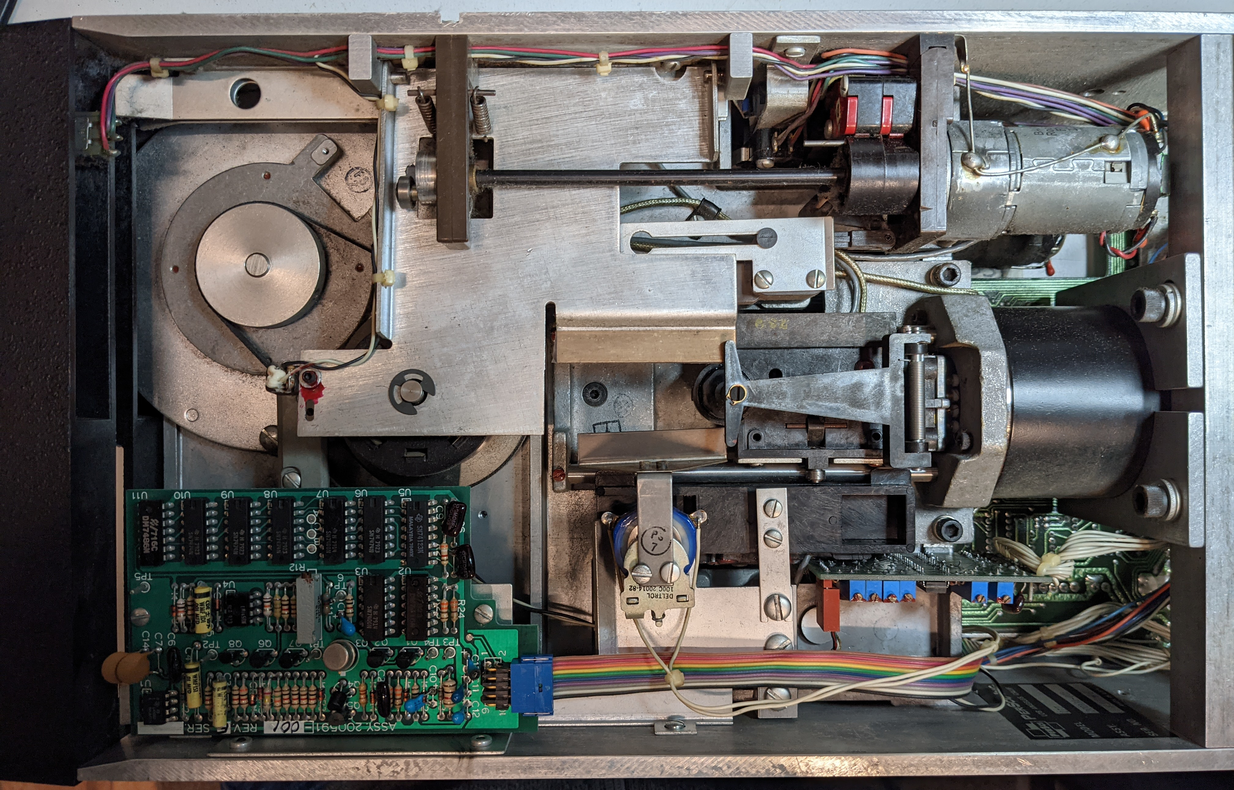
The drive has 4 main PCBs which are connected by a whole range of cables. The largest board covers almost an entire side of the drive and amazingly can be swung open using a hinge (after removing two screws). When testing powering up the drive with the original PSU, a few components failed in a rather dramatic way - sound, smoke and flames - which hopefully only need replacing, and didn't cause too much damage to the rest of the circuitry. Everything seems to be fairly discrete logic, there aren't any surface mount components to be seen in the entire assembly, and the schematic reference contains detailed circuit diagrams of the whole drive.
Before disassembling the entire drive, it was powered on using the original PSU (which was measured producing the correct voltages, although these weren't tested under load). A couple of components on the PSU (1 TO3 power transistor and a chunky resistor) and some capacitors and resistors on the drive itself promptly exploded. The 24V line on the PSU measured at 40V after powering it on again with the drive disconnected - although this was still with the failed components in place.
When desoldering components from the PCBs, it seems that the through-hole plating and the PCB traces are extremely delicate - pulling components out even slightly out of alignment with the hole can easily pull the through-hole-plating and the surrounding trace off with the component. Not sure what is the best way to deal with this except to be extremely careful.
Load/Eject Motor Assembly
See p26 of the schematic diagrams pdf - "Schematic Eject Motor Assembly".
The disk load/eject mechanism is quite a clever (and remarkably simple) electromechanical system which responds to the insertion of a disk using the eject motor cam to press the upper spindle cone into the central disk hole (locking the disk in place and allowing the spindle motor to engage the disk media). Disk presence is detected with a third microswitch (S-3 for side 0, S-7 for side 1). The connectors P18 and P17 have only pins 1 (Disk Presence), 3 (+24V) and 6 (GND) connected - the remote eject relay is not present. The eject motor has a cam on its axle which tracks the rotation position using two microswitches (CAM S-2, S-1 for side 0, S-6 & S-5 for side 1). Pressing the eject button with the disk in place (and the mechanism in the "loaded" position) triggers the motor to spin further, releasing the disk and pushing it out of the drive using via a plastic arm thingy.
When first inspecting the drive, the drive transport card was in place (see the removed card in the photo below), which was removed by manually rotating the eject motor axle. Noting that the eject system is designed based on some mechanical constraints - particularly, that the state of the cam switches must always be consistent with the state of the disk presence switch (eg. it is "impossible" for the system not to detect a disk when the mechanism is in the "loaded" state.) Basically it can short circuit itself if you fiddle with it by either releasing the disk presence switch when it is in the "loaded" position (probably), or when the disk presence switch is held down after the "eject" mechanism should have pushed the disk out of the drive (tested).
Disconnecting the motors from the logic board and powering them from a separate PSU - firstly at 12V as written on the motors themselves, then at 24V according to what the actual drive would be doing, blew up quite a few of the (fortunately easily replaceable) components attached to the motors. It turns out that tantalum capacitors are highly susceptible to damage by incorrect polarisation (one placed across motor terminals on either side of the ferrite bead assembly, on each motor - 4 in total). And that the motor terminal wires are alternating polarity on each side (eg. red is ground on side 1, black is ground on side 0). And that diodes will burn out if they are overloaded. Then that tantalum capacitors too will release smoke if they have been damaged somehow. It's possible that the initial test of the drive failed in part due to the eject motor mechanism being in the wrong position - oops.
After removing all of the (now broken) protection caps & diodes from the motor terminals it was possible to power the motors through the connectors P18, P17, with the motor eject mechanism in the "unloaded" position, and not have anything blow up. Inserting a disk into the drive caused the motor to rotate into the "loaded" position, then stop. Pressing the eject button briefly caused the motor to rotate further and eject the disk, then stop in the "unloaded" position. It works, hooray! (Both sides tested and working!) Now to buy the replacement caps & diodes.
Lamp Amplifier PCB
Trying to remove all the PCBs for closer inspection for failed components, maintenance & testing came to a halt at the Lamp Amplifier circuit. It is attached to the head actuator assembly in such a way that accessing it conveniently it is not possible without unmounting the entire voice coil and head actuator assembly from the drive casing. In the process of unsuccessfully trying to remove parts of the assembly, finding that parts cannot be removed fully due to limited space, then reattaching them, there will inevitably be future headaches realigning the heads and recalibrating the drive. I'm still not sure what "Lamp Amplifier" actually means; the board seems to be responsible for the head positioning which relies on a linear optical encoder. It outputs "track sense", "coarse position sense" and "fine position sense" signals on P5.
Double Density Data Separator PCB
Seems to decode the raw "Read Data" signal into the separated Clock and Data signals. All 3 are present in the drive data cable spec, and only the Read Data signal is used by the AM-200 FDC - it may even be possible to operate the drive with the S-100 controller without this board being connected [untested]. The separate data/clock lines are pulled high with 1K resistors on the data/interface board.
Component C13 (1uF 35V tantalum capacitor) exploded during intial testing - interestingly this was just between 24V supply and GND. The failure may have been caused by a PSU overvoltage on the 24V line. Nothing else on the board seems visibly damaged.
Data & Interface PCB
Largest logic board in the entire drive - has connectors leading to the other boards, as well as the drive's power and data connectors.
During initial power-on, R56 (10R 0.25W) and R121 (10R 0.5W) expressed an affinity with magic smoke. R121 is connected in series between the 24V supply and the eject motor assembly P18 (side 0). R56 connects 24V to some part of the read/write circuitry for head 1, a mirror of R42 for head 0. Not sure why R56 failed and R42 did not. Need to test C33, C34, C29, C30, Q9, Q16.
Q16 is working fine but tantalum cap C33 is shorted, Q14 is suspicious (although removing it from the circuit to test isn't helping - don't have good equipment to test MOSFETs). Checking the circuitry around R56 - it's possible that Q16 was turned on which may have damaged Q15 & Q14. Ceramic cap C34 is OK.
Photos
Here are some photos taken of various bits and pieces. Order is left-to-right, top-to-bottom.
Persci 277 drive (rear), side-view, side-view with PCB lifted up, other side view, drive protection transport card
ACP S-100 backplane + underside, original S-100 PSU, Disk drive PSU (CP272A)
AM-100 CPU board 1, AM-100 CPU board 2, AM-200 FDC board, AM-300 Serial IO board, IMS 16K RAM board (matte IC variant), IMS 16K board (gloss variant), ACP diagnostics board
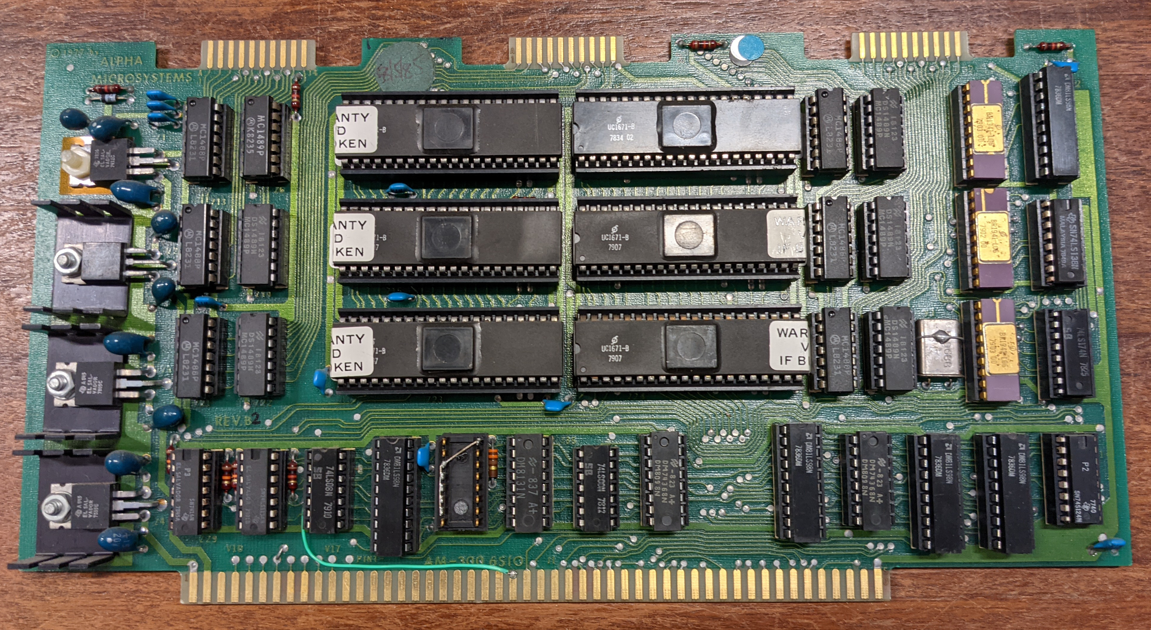
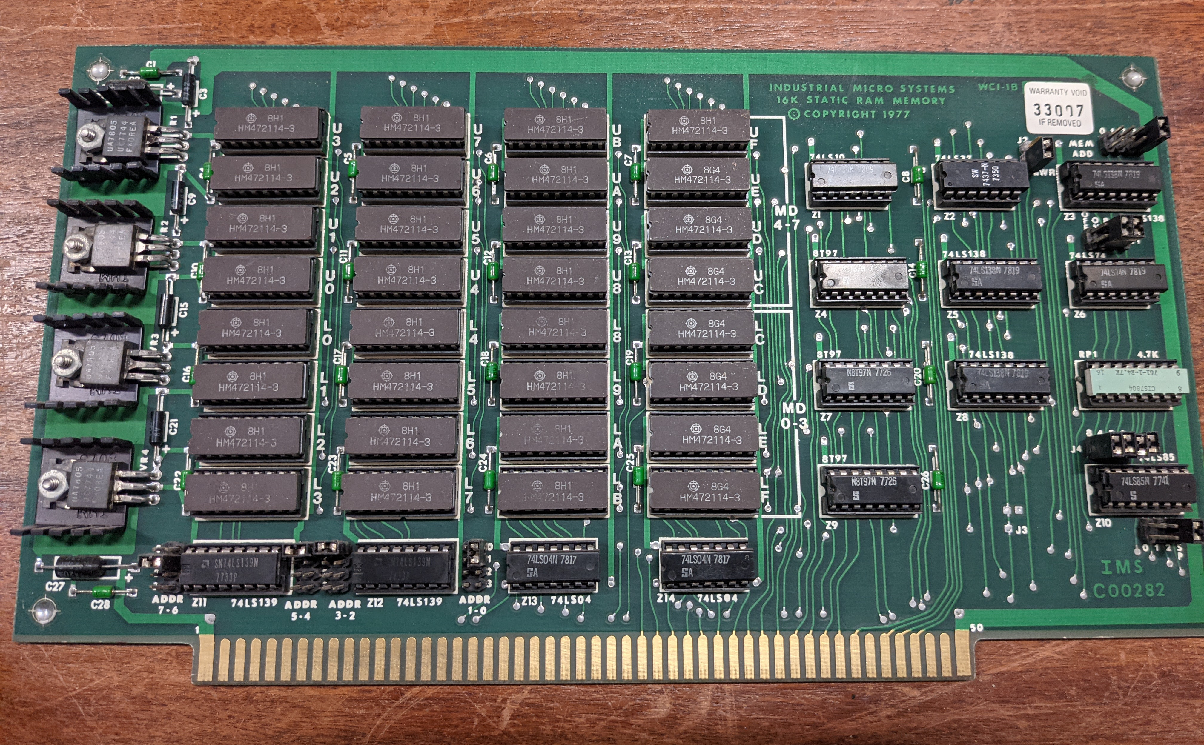
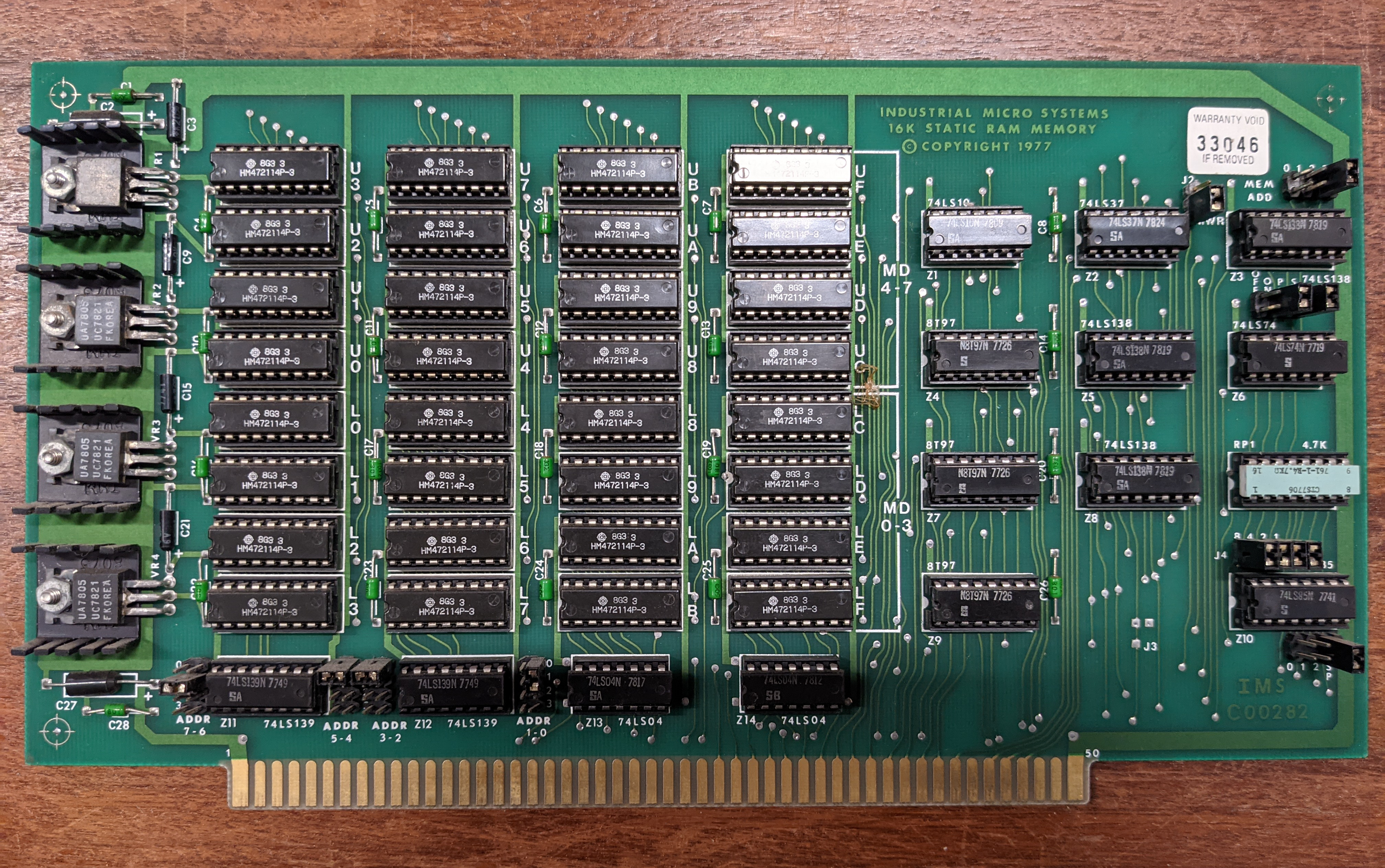
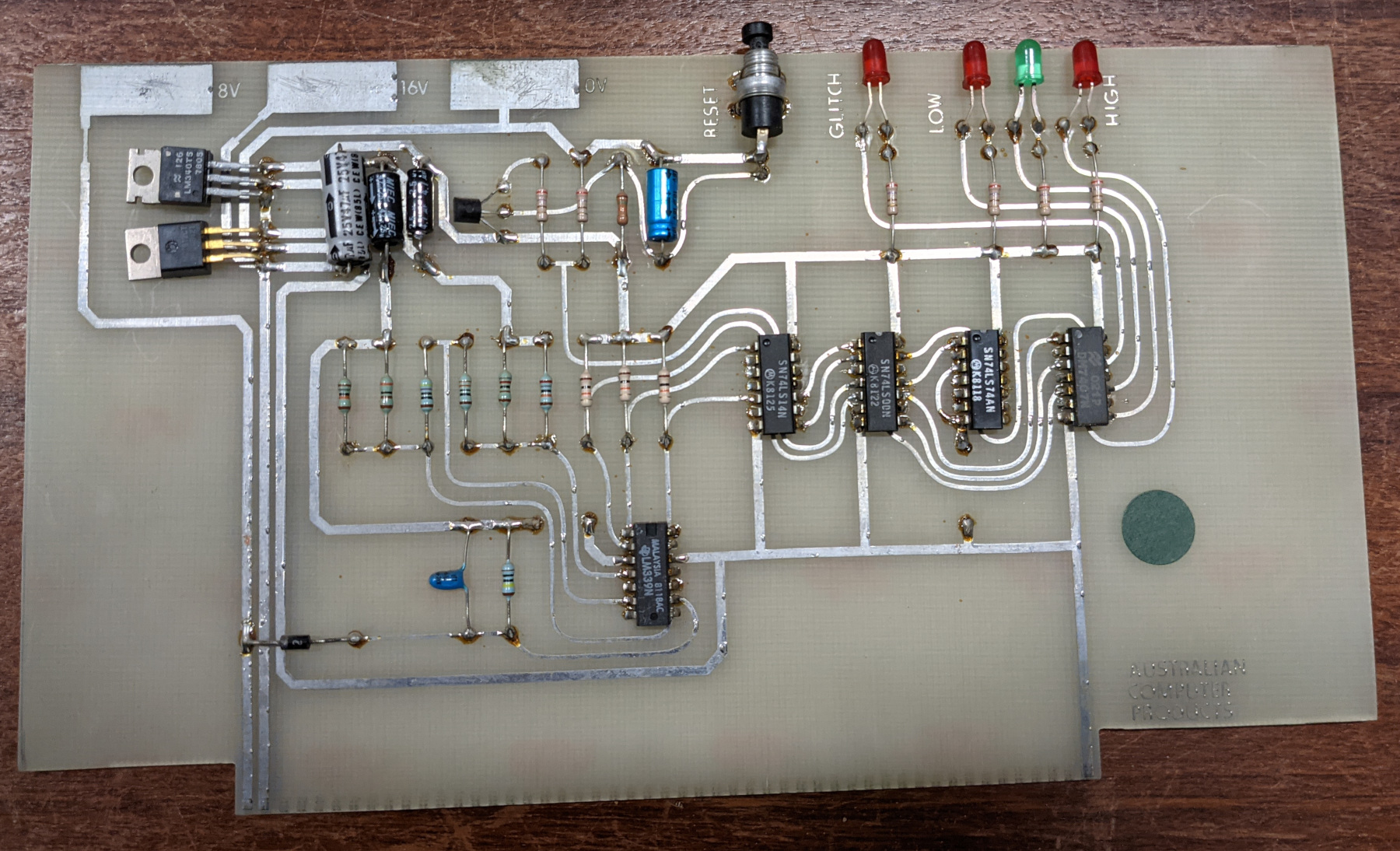
M2896 Disk drive (label only)
Resources & References
There are some really good websites out there with information & documentation for most if not all of these ancient computer bits. The documents uploaded above came from a mix of these sites.
Note: this was basically a dump of my browser session when writing this page. Not very well organised but here it is.
http://s100computers.com/Hardware%20Folder/IMS/16K%20Static%20RAM/16K%20Static%20RAM.htm
http://s100computers.com/Hardware%20Folder/Alpha%20Micro/AM-200%20FDC/AM-200%20FDC.htm
http://s100computers.com/Hardware%20Folder/Alpha%20Micro/AM-310/AM-310.htm
http://s100computers.com/Hardware%20Folder/Alpha%20Micro/AM%20300/AM-300.htm
http://s100computers.com/Hardware%20Folder/Alpha%20Micro/AM-100/AM-100.htm
http://ampm.floodgap.com/www/amos.htm - About AMOS (Alpha Micro OS)
http://ampm.floodgap.com/www/links.htm - More links to Alpha Micro stuff
https://archive.org/details/bitsavers_alphaMicro200FloppyDiskController_4385602/page/n1/mode/2up